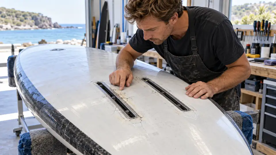
A reliable foil track box installation is a load-path problem before it is a lamination problem. The twin tracks must be positioned for the board-and-foil system, held parallel and coplanar, bonded into a dense structural insert, and connected to enough sound surrounding skin to spread mast loads. Adding carbon only around the slot cannot compensate for weak core, poor bonding, incorrect geometry or an unverified cure.
This guide is written for foil-board brands, product developers, repair specialists and buyers evaluating a factory. It covers new construction and the questions that should be answered before a retrofit. It does not prescribe one universal layup: board structure, rider load, foil leverage, materials and manufacturing process all change the engineering requirement.
Read the failure before reaching for resin
A hairline crack at the track edge often attracts attention because it is visible. Yet the initiating fault may sit deeper: crushed low-density foam, a dry bond line, a hard edge that concentrates strain, water-contaminated core, track movement, or repeated leverage from a mast plate that was not seated correctly. Grinding the crack and covering it can hide rather than remove the cause.
| Observed symptom | Possible underlying cause | What to verify |
|---|---|---|
| Crack along one rail | Local flex, resin-rich corner, poor skin transition or off-axis loading | Track movement, laminate continuity and plate seating |
| Both tracks rock together | Insert-to-core or insert-to-skin separation | Extent of delamination by qualified inspection |
| Fastener will not clamp | Incorrect bolt length, damaged thread or debris in channel | Hardware compatibility and remaining thread engagement |
| Darkness, weight gain or moisture | Water path at track, vent or damaged skin | Moisture extent before sealing or laminating |
| Mast plate sits unevenly | Tracks not coplanar, cured resin proud of the surface or distorted skin | Flatness across both rails and plate contact |
| Board consistently pulls or trims strangely | Track pair off center, nonparallel or wrong installation angle | Centerline, parallelism and angle against design datums |
Stop using the board when a track moves, the surrounding skin sounds broadly detached, water is present, or cracks grow under load. A cosmetic diagnosis is not enough for a structural mount.
The track is only the visible end of the load path
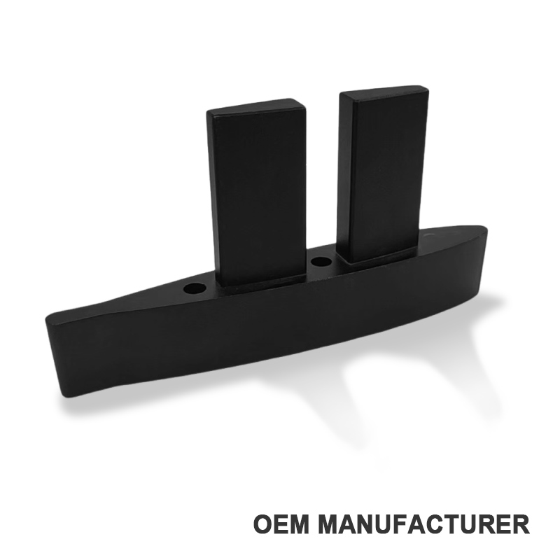
The foil produces lift below the board while the rider applies force above it. The mast turns those forces into bending, shear and torsion at the mounting plate. Track nuts load small areas inside the rails; the rails load their surrounding insert; the insert must then distribute force into the board skins and sandwich core. Every interface matters.
That explains why a locally stiff patch can still fail. If it ends abruptly over weak foam, the stiffness change simply moves peak strain to the patch edge. A sound design creates a gradual transition from the tracks, through a high-density hardpoint, into a wider region of intact structure.
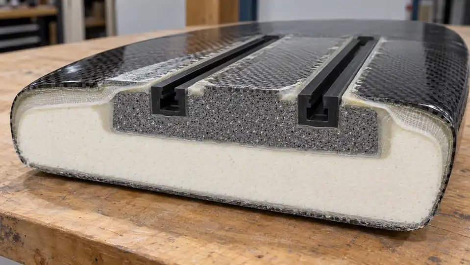
Four interfaces deserve separate acceptance criteria
- Hardware to rail: the correct nut and bolt geometry must clamp without bottoming out.
- Rail to insert: surface preparation, gap control and adhesive wet-out must resist peel and shear.
- Insert to board: the replacement core must contact sound material with no unfilled voids.
- Reinforcement to skin: fibers must overlap prepared, compatible laminate far enough to transfer load progressively.
The AFS Hydrofoil user guide offers a small but important hardware warning: select screw length carefully so the screw does not bottom in the box. This is a setup detail, yet it illustrates why installation quality and user hardware cannot be separated completely.
Placement is a system decision, not a distance copied from another board
There is no universal tail-to-track number for every foil board. Usable position depends on foil geometry, fuselage relationship, rider stance, board outline and rocker, intended speed, discipline and how much adjustment the rails provide. Copying a measurement without the original design datums can place the foil outside the rider’s useful stance range.
For a new model, start with the complete system: target foil families, front-wing lift center range, stance positions, rider range and the board’s running attitude. Model the adjustment envelope, then confirm it with prototypes. For an existing design, preserve the manufacturer’s specified reference unless the change is deliberately engineered and tested.
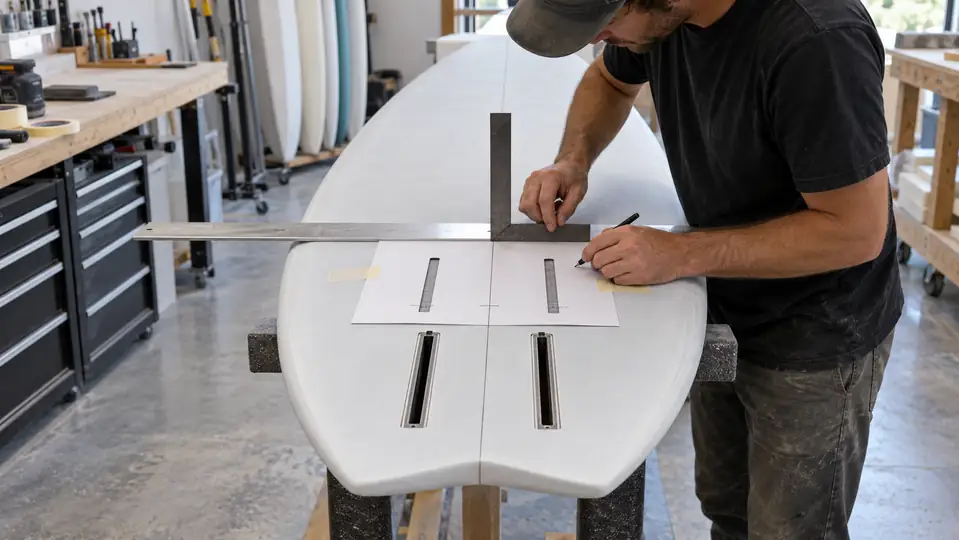
Geometry checks that belong on the drawing
- fore-aft position from an unambiguous design datum;
- track spacing and usable adjustment length;
- each rail’s parallelism to the board centerline;
- parallelism between rails;
- coplanarity and flushness at the mounting surface;
- mounting-plane angle relative to the board’s designed reference plane;
- clearance from inserts, vents, handles, straps and internal structure.
Foil Tec’s installation instructions use a jig and emphasize alignment during bonding. That is useful process guidance. A production specification should go further by defining measurable tolerances and the inspection method, so “looks straight” is not the acceptance standard.
A go/no-go decision before cutting the board
A retrofit begins with evidence, not a router. Confirm the board’s construction, core condition, local skin schedule, hidden components, available bonding area and whether the intended foil loads are compatible with the structure. If drawings are unavailable, uncertainty must be treated as a design risk.
| Proceed to engineering review when… | Pause the retrofit when… |
|---|---|
| The construction and sound bonding boundaries are known | The core is wet, crushed or broadly delaminated |
| A qualified builder can create a continuous hardpoint | The only plan is to glue rails into low-density foam |
| Track position is supported by system geometry | Position was copied from an unrelated board |
| Cure, alignment and inspection can be controlled | The rails cannot be held accurately throughout cure |
| A validation plan exists before riding | No one has defined proof-load or inspection acceptance |
The SURF workshop on foil-box reinforcement is valuable because it shows that reinforcement is more extensive than the opening itself. Its repair-oriented example should still be adapted to the actual board, process and intended loads rather than copied as a universal laminate recipe.
Build the hardpoint, not just the hole
During foil track box installation, the routed region should terminate in sound, dry material. Weak core is replaced with a structural insert selected for compressive, shear, fatigue, bonding and environmental performance—not merely because it is easy to shape. The insert geometry should avoid sharp internal corners and give the adhesive a controlled, continuous bond line.
Before bonding, verify resin and substrate compatibility, prepare surfaces using the material supplier’s process, remove dust without contaminating the surface, and dry-fit the entire assembly. Tracks should be protected from resin ingress while still allowing the bonding faces to wet correctly. Excess adhesive is not a substitute for correct gap design.
Why high-density inserts help
Low-density board foam is efficient for shape and flotation but can crush under concentrated mounting loads. A denser insert spreads those loads over a larger area and supports the rail walls. It does not work in isolation: an inadequately bonded block can detach as one stiff piece, and an abrupt block edge can create a new hinge line.
Reinforcement must bridge into the board skin
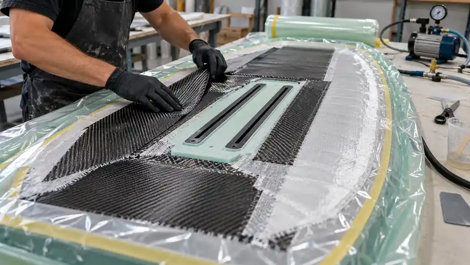
The laminate has to manage loads in more than one direction. Fiber orientation, overlap, taper, resin content, consolidation, corner radii and continuity around the insert influence the result. Carbon can provide high stiffness, while glass may contribute toughness, electrical isolation or a more gradual transition in a hybrid schedule. The correct combination depends on the design.
More layers are not automatically safer. Excess local stiffness, resin-rich corners, bridged fabric, trapped air or poorly tapered edges can reduce durability. A controlled process records material batch, ply identity, orientation, overlap, resin system, mix ratio, vacuum or consolidation data, cure temperature and time.
Cure first, machine second
The fixture must hold rail spacing, position, angle and coplanarity throughout cure—not only during the dry fit. After cure, remove protection carefully, clear channels without damaging rail walls, seal any permitted machined edges, and remeasure geometry. Forcing a mast plate onto misaligned tracks converts a dimensional defect into assembly stress.
The foil track box installation is not finished at demolding
Visual inspection can find resin starvation, bridging, exposed core, blocked channels and finish defects, but it cannot prove structural capacity. Production quality control should combine dimensional inspection with a validated structural test plan. The test must use representative board construction, hardware and load direction.
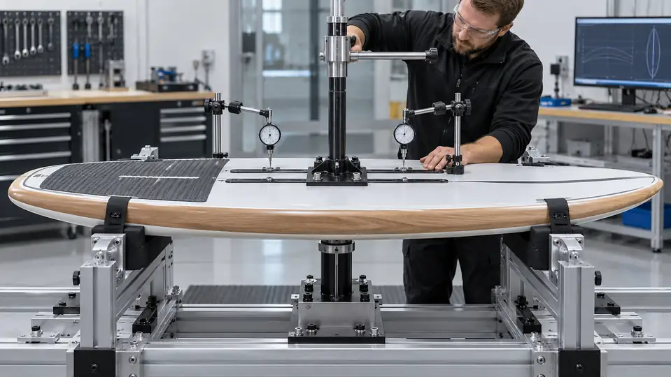
An OEM acceptance plan worth asking for
- Incoming control: rail material, dimensions, straightness, channel and nut compatibility.
- In-process geometry: position, spacing, centerline alignment, angle and fixture verification.
- Process records: core and adhesive identification, surface preparation, mix data and cure log.
- Finished dimensions: parallelism, coplanarity, flushness and usable channel length.
- Bond inspection: agreed visual criteria plus a validated tap, ultrasonic or other suitable method where applicable.
- Structural validation: engineering-defined proof load and, for new models, representative cyclic or fatigue testing.
- Water integrity: a method and acceptance limit appropriate to the complete board construction.
- Traceability: model, batch, materials, process record, operator and inspection result.
A “maximum load” number without fixture geometry, direction, lever arm, sample count and failure criterion is not meaningful evidence. Brands should agree on a golden sample and a signed control plan before volume production. Unity Sports’ hydrofoil manufacturing overview explains the broader composite process; a track-box project should add board-specific structural validation.
Once on the water, tune the mast—do not redesign the box
If the board and foil manufacturer provide a starting position, use it. Otherwise, the middle of the usable tracks is a practical test baseline for a compatible system. Move the mast in small increments—often 5 to 10 mm—record each change, and alter one variable at a time.
Moving the mast forward generally increases the foil’s lift influence under the rider and can make the nose rise sooner. Moving it aft generally reduces that tendency and may calm an over-lifting setup. These are system-level tendencies, not guarantees; foot position, stabilizer, shim, front wing and speed also change trim. Tonic Mag’s mast-position explanation is a useful rider-level reference for this tuning relationship.
Inspection habits that prevent a small defect becoming a failure
- Rinse salt and grit from rails and hardware, then let the assembly dry.
- Before every session, check for cracks, rail movement, soft spots and an uneven plate seat.
- Use compatible hardware and the board or foil maker’s tightening guidance.
- Do not use bolt torque to pull a distorted plate or noncoplanar tracks flat.
- After a hard grounding or impact, remove the foil and inspect the mount before riding again.
- Track any crack with dated photographs; growth is a stop-use signal, not a cosmetic issue.
For component selection, see Unity Sports’ foil track box and hydrofoil mounting plate pages. Brands developing a complete board can also review our foil board manufacturing capabilities and discuss drawings, target systems and validation through the project inquiry page.
Questions buyers and builders ask
Can foil tracks be bonded directly into EPS foam?
Not as a dependable structural shortcut. Low-density foam is vulnerable to concentrated compression and shear. A properly engineered installation normally uses a stronger insert and reinforcement that transfers load into sound surrounding structure.
How far should the tracks be from the tail?
There is no safe universal number. Position must be derived from the intended foil geometry, stance range, board reference planes and adjustment target. Use the board designer’s datum or validate the complete system with prototypes.
Does adding more carbon fix a weak installation?
No. Carbon over a weak core, contaminated bond or discontinuous load path can make the surface stiffer while leaving the initiating defect in place. Diagnose the structure first and design the entire transition.
Why do both rails need to be coplanar?
A mast plate is designed to clamp against one plane. If one rail is higher or twisted, tightening can preload the plate, concentrate load, distort the skin and make alignment inconsistent.
What should an OEM provide before production approval?
At minimum: controlled drawings and tolerances, material and process records, dimensional inspection, a representative structural validation report, water-integrity criteria, traceability and approved samples. Requirements should be agreed for the actual board and target foil systems.
The practical conclusion
A durable Foil Track Box Installation cannot be judged by a neat carbon patch alone. Start with system position, create a continuous hardpoint, control geometry during cure, and verify the finished structure with measurements and representative tests. For buyers, the most revealing supplier question is not “How many carbon layers do you use?” It is “Show us how the load moves from the mast plate into the board—and the records proving that path is controlled.”