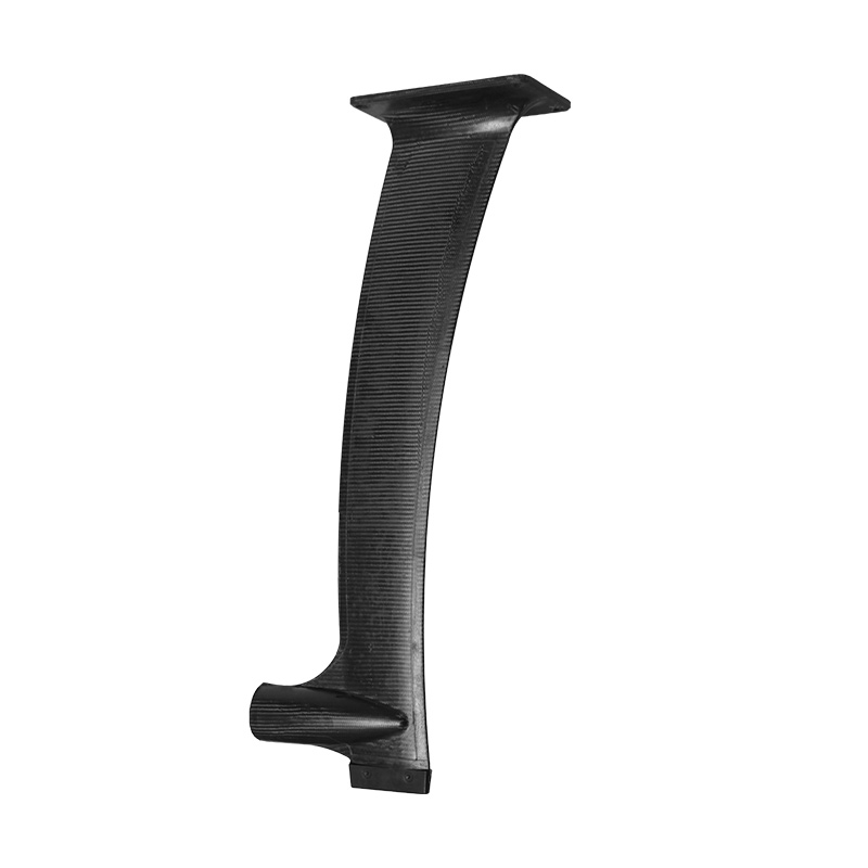
Carbon fiber layup orientation determines where a laminate is stiff, where it can carry shear, and where it remains vulnerable. A 0° ply mainly reinforces the reference direction, ±45° plies help carry in-plane shear and torsion, and 90° plies reinforce the transverse or hoop direction. The percentages, order, material form, resin system, geometry, interfaces and manufacturing quality then decide how those contributions work together.
The short engineering answer
Do not ask for “a strong carbon layup” without defining direction. Mark a 0° datum, describe the real load paths, identify torsion and transverse demands, and state how the finished part will be validated. A familiar sequence such as [0/±45/90]s is a teaching starting point—not a universal production specification.
This guide is written for product developers, sourcing teams and engineers preparing an OEM carbon-fiber project. It explains the language needed for a productive design-for-manufacturing review. It does not replace application-specific laminate analysis, safety factors, prototype testing or approval by the responsible engineer.
Carbon fiber is directional before it is strong
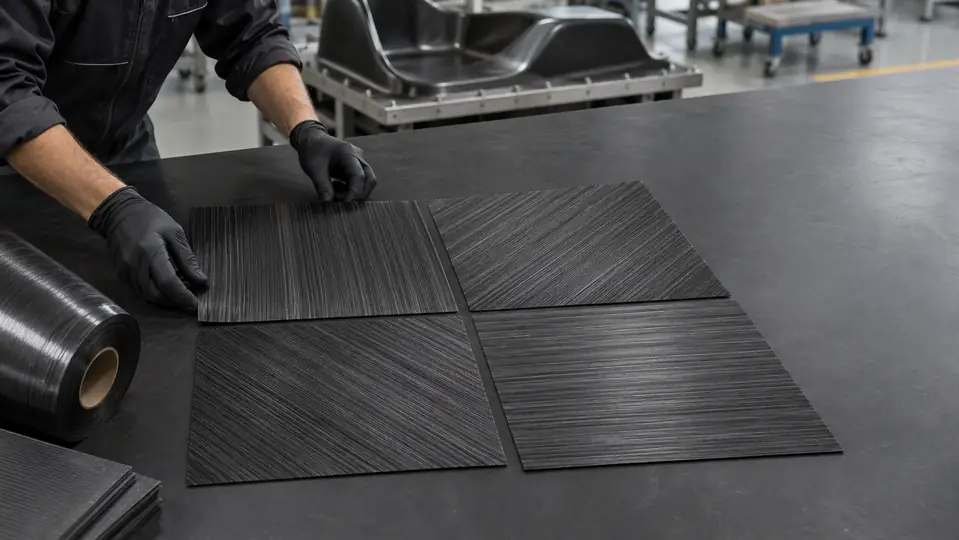
Metals are often treated as having similar elastic behavior in every in-plane direction. A carbon-fiber ply is different. Continuous fibers provide their greatest stiffness and load-carrying contribution along the fiber direction; across the fibers, behavior depends much more on the matrix, fiber–matrix interface and neighboring plies. The finished laminate combines all of those directional layers.
This is why two black plates of the same thickness can feel completely different. One may be dominated by fibers running lengthwise and resist bending in that axis. Another may distribute fiber among several angles and accept loads from multiple directions, but use less of its total fiber in the single dominant direction.
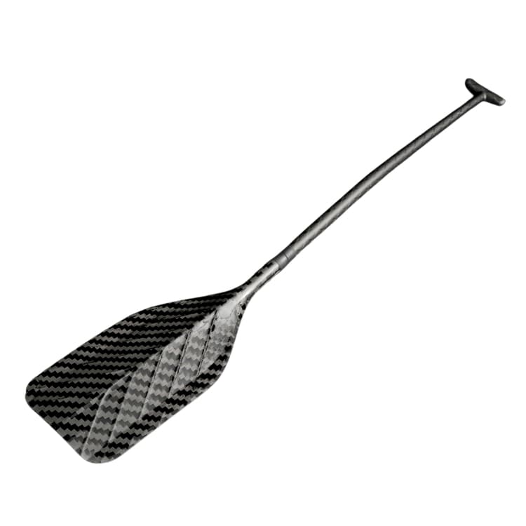
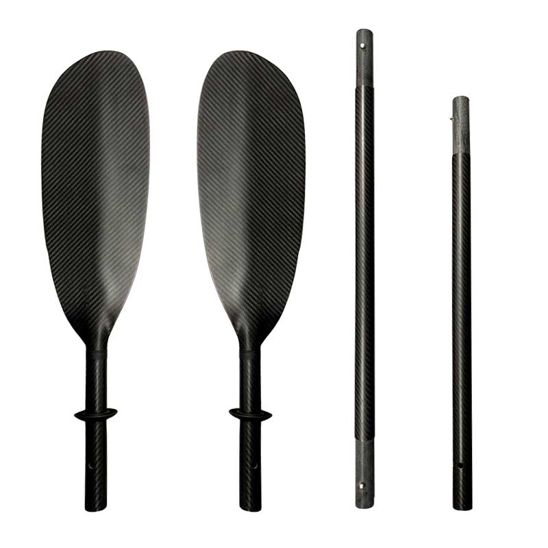
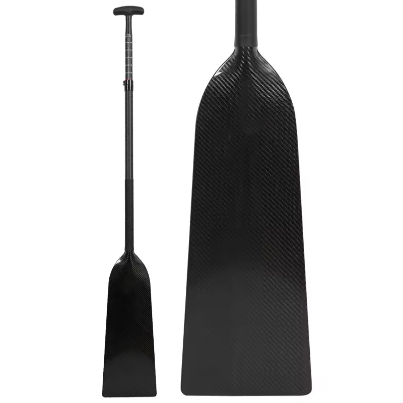
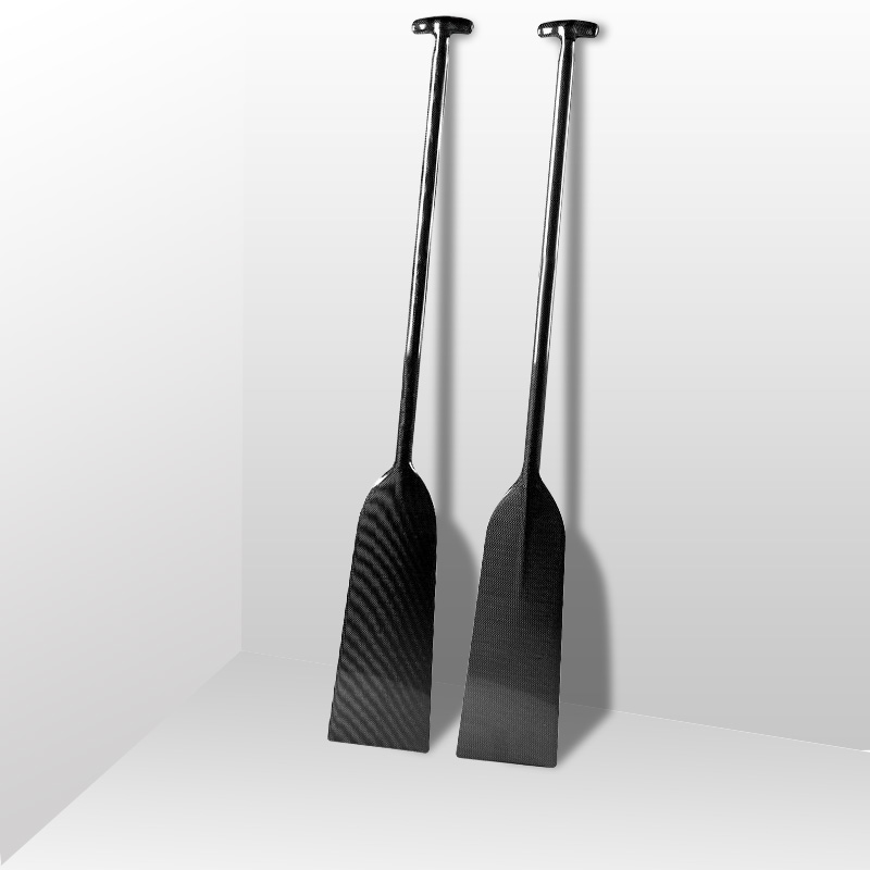
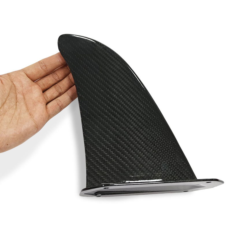
The visible weave is not a reliable map of the internal structure. A cosmetic 3K twill face can cover unidirectional, woven, multiaxial or locally reinforced plies underneath. A buyer who approves only the surface appearance has not yet approved the load path.
What 0°, ±45° and 90° plies actually contribute
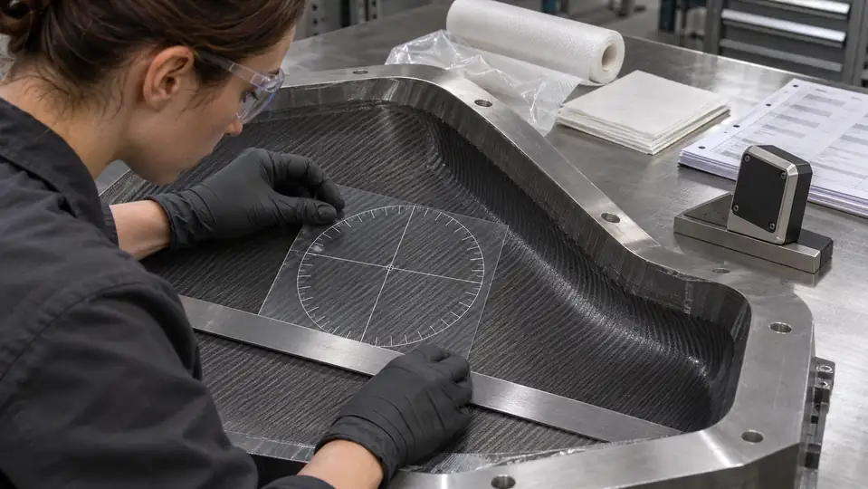
The angle is measured from a reference axis chosen for the part. On a rectangular plate, 0° may follow the long edge. On a tube, 0° normally follows the tube axis. On an irregular shell, the drawing needs a datum or coordinate system; otherwise an angle has no controlled meaning.
| Ply orientation | Primary contribution | Where it often matters | What it cannot solve alone |
|---|---|---|---|
| 0° | Axial tension/compression and bending stiffness along the defined reference direction | Long beams, shafts, spars, rails and dominant lengthwise load paths | Transverse splitting, unsupported cross-loads and torsion |
| +45° / −45° | In-plane shear transfer and torsional response | Torque tubes, webs, shells, corners and load transfer around interfaces | They normally need both signs; one sign alone can introduce unwanted coupling |
| 90° | Transverse in-plane or hoop reinforcement | Tube crushing/hoop loads, panel width, splitting resistance and crosswise interfaces | Primary lengthwise stiffness when the dominant load is axial |
| Mixed angles | Tailored response across multiple load directions | Real components with bending, torsion, impacts, holes and bonded joints | A universal percentage that works for every geometry and duty cycle |
Gurit’s Guide to Composites explains that laminate behavior depends on fiber alignment and that stacking sequence, symmetry and balance all matter. The Composites Knowledge Network likewise describes how UD fiber has its highest stiffness along the fiber and how angled layers can build a multi-directional laminate.
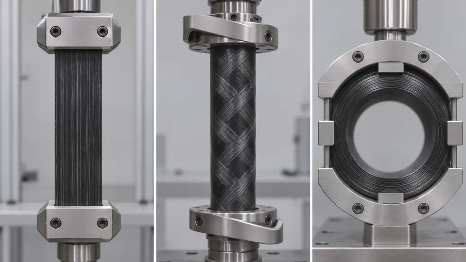
The same angle means different work in a plate, tube or shell
Carbon fiber layup orientation should be interpreted through geometry, not memorized as a list.
| Geometry | 0° normally means | ±45° normally helps with | 90° normally means | Buyer question |
|---|---|---|---|---|
| Flat plate or beam | Along the selected length or main span | Panel shear and diagonal distortion | Across the width | Where are supports, point loads, holes and free edges? |
| Tube or shaft | Axial direction | Torque and combined bending/torsion | Circumferential or hoop direction | Is failure driven by bending, twist, crushing, clamp pressure or fatigue? |
| Molded shell | A defined product datum or primary load path | Shear flow around curves, corners and cut-outs | Crosswise support relative to the datum | How will ply direction follow changing curvature without wrinkles or bridging? |
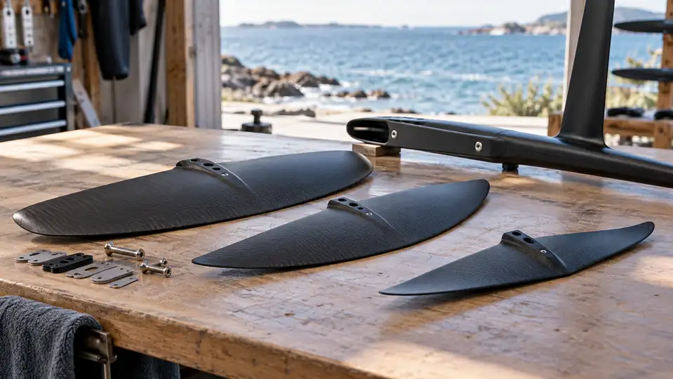
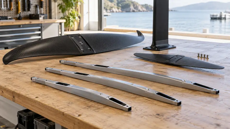
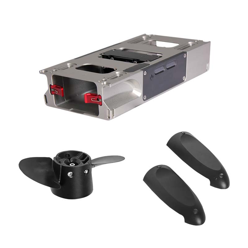
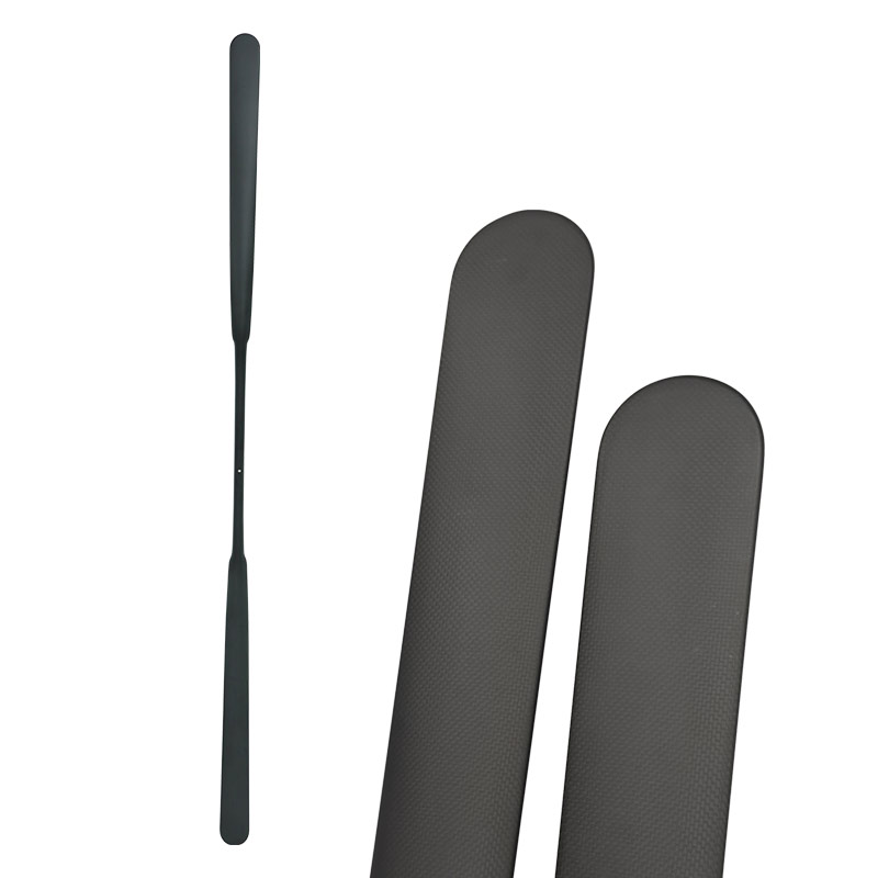
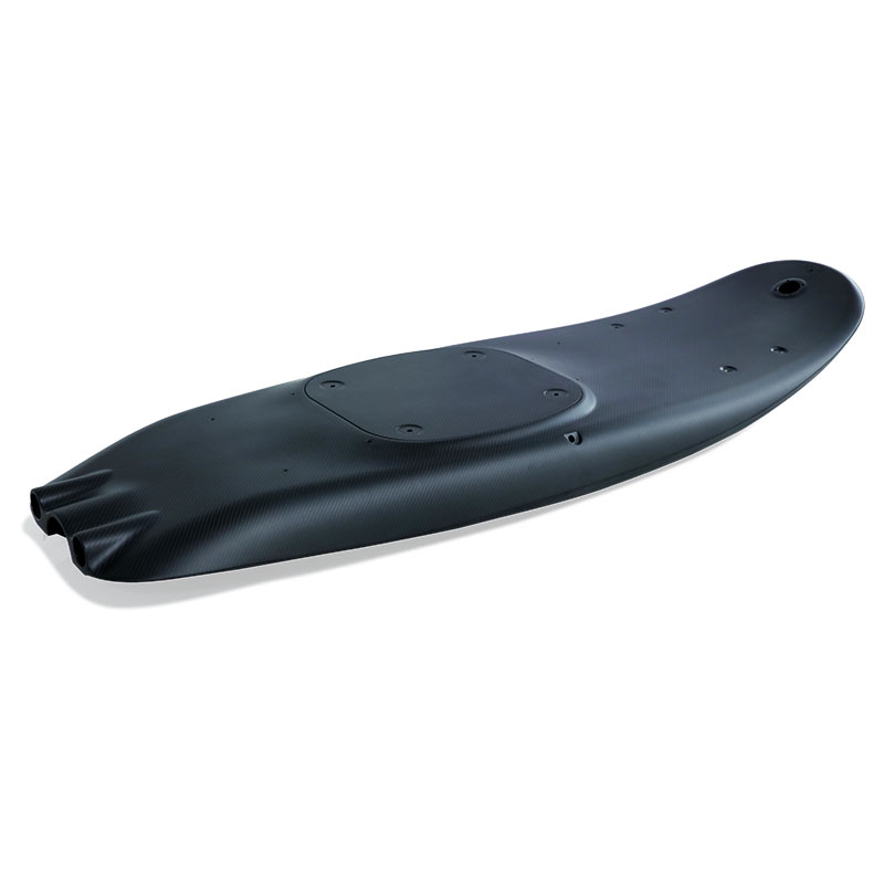
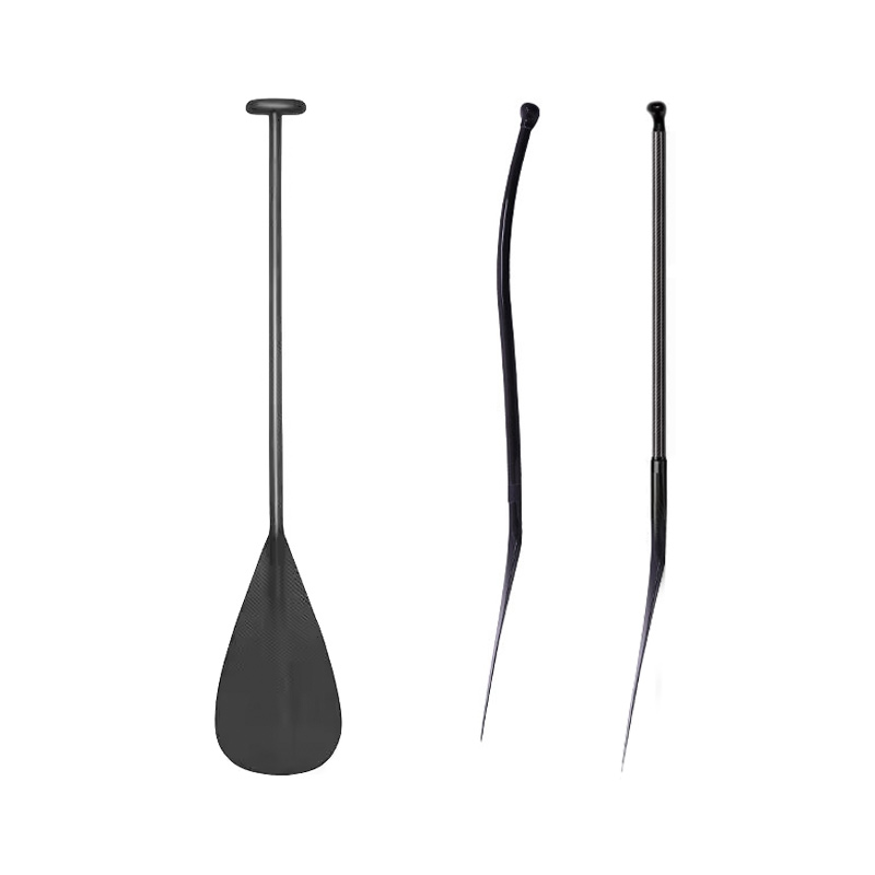
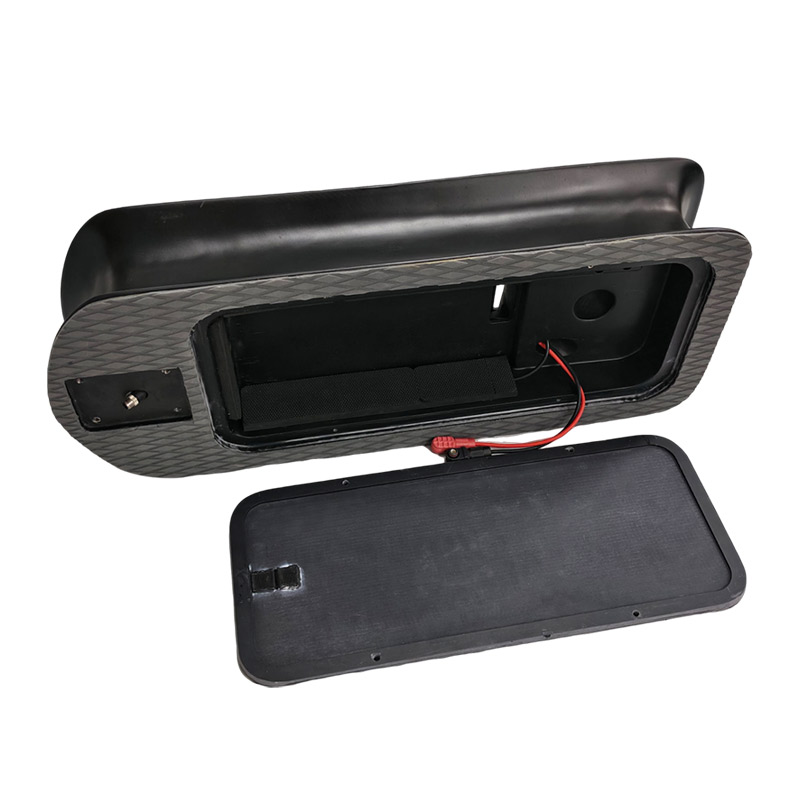
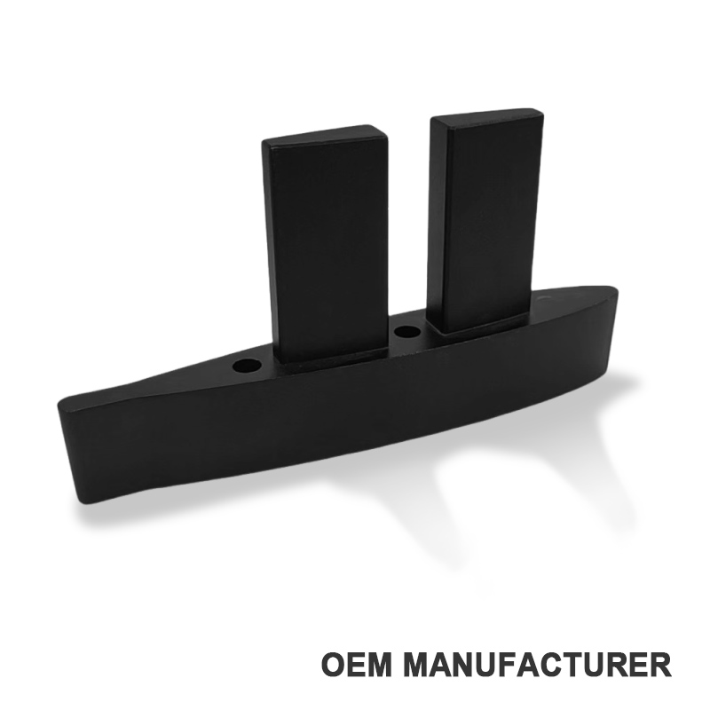
A long carbon mast or shaft illustrates the point: axial fiber can provide bending efficiency, but the component also needs a laminate that manages torsion, local crushing and interfaces. See Unitysurf’s discussion of a high-modulus carbon-fiber mast for the product context. A molded carbon-fiber battery box presents a different problem—corners, openings, inserts, sealing faces and local fastener loads can matter as much as a single global axis.
Balanced, symmetric and quasi-isotropic are not synonyms
A balanced laminate matches positive and negative angles
In classical laminate terminology, a balanced laminate contains matching +θ and −θ plies of the same material and thickness. A +45° ply is therefore normally paired with a −45° ply. The purpose is to control in-plane coupling; it does not automatically make the laminate symmetric or equally stiff in every direction.
A symmetric laminate mirrors the mid-plane
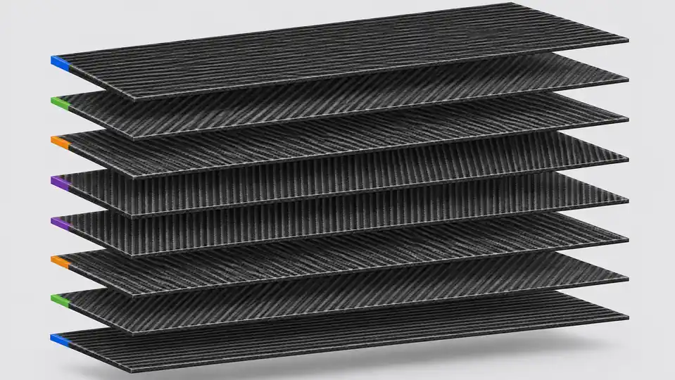
A symmetric stack mirrors ply material, angle and distance about the laminate mid-plane. For example, [0/+45/−45/90]s expands to a mirrored eight-ply stack. Symmetry is used to suppress extension–bending coupling under the assumptions of classical laminate theory. It does not guarantee a perfectly flat part: tooling, cure gradients, material variation and handling can still contribute to distortion.
Quasi-isotropic describes in-plane elastic behavior
A quasi-isotropic laminate is arranged to make in-plane extensional stiffness approximately independent of direction. NASA’s composites terminology reference lists [0/45/−45/90] as a typical orientation set. “Quasi” matters: the laminate is not identical in through-thickness behavior, impact response, fatigue, hole bearing or every failure mode.
Ply count is not enough because stacking order changes bending
Two laminates can contain the same number of 0°, +45°, −45° and 90° plies yet behave differently in bending. Plies farther from the mid-plane contribute more to flexural stiffness in their direction. Moving lengthwise reinforcement toward the outside can therefore change bending response without changing total thickness or angle percentages.
Stacking order also affects interlaminar stress, surface durability, ply drops, damage progression and manufacturability. Large blocks of the same angle may be undesirable in some designs; placing an unsupported 90° ply at a free edge can expose a matrix-dominated direction; and abrupt thickness changes can create stress concentrations. None of these issues can be solved by a one-line “50% 0°, 25% ±45°, 25% 90°” rule.
For a real part, the designer should review at least:
- membrane, bending, shear and torsional load cases;
- tension and compression on both sides of the part;
- holes, inserts, bonded joints, clamps and concentrated loads;
- impact, fatigue, moisture, temperature and UV exposure;
- minimum radii, drape, bridging, wrinkles and permissible ply splices;
- tool side, bag side, cosmetic face and machining allowance;
- inspection access and the evidence required for acceptance.
Unidirectional tape and woven cloth solve different problems
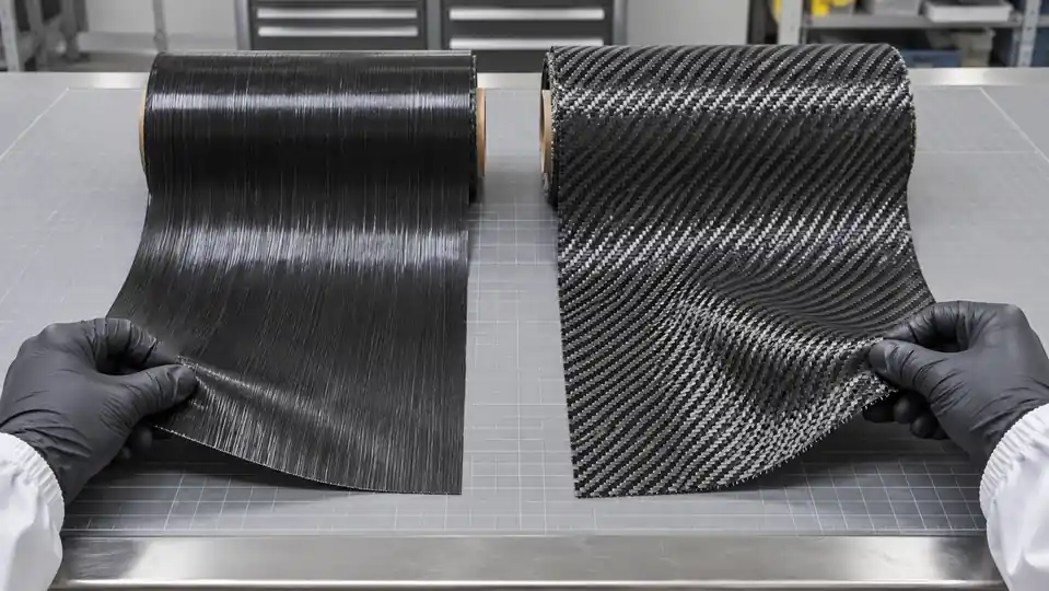
Unidirectional material places most continuous fiber in one direction, making it efficient when the primary load path is known. Woven cloth places fibers in two directions in one ply and is easier to handle around some shapes, but its interlacing creates crimp. Non-crimp multiaxial materials hold several straight fiber directions together with stitching, trading different handling and processing characteristics.
A woven surface may be chosen for appearance, handling or damage tolerance, while UD plies underneath carry the dominant structural loads. That does not mean woven is decorative or UD is always superior. The correct form depends on shape, process, fiber volume, drape, labor, defect risk and required performance.
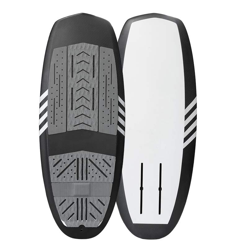
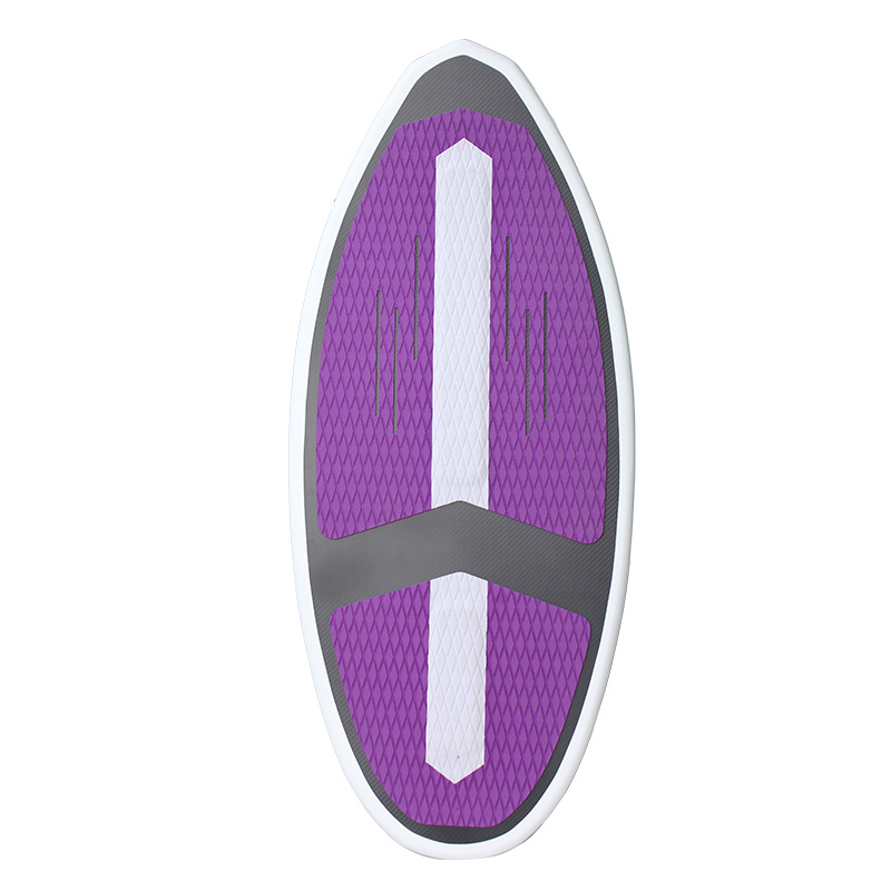
Unitysurf’s carbon-fiber surfboard building guide shows how product construction may combine fabrics, local reinforcement and a core. The orientation principles remain relevant, but a sandwich board, solid plate and hollow tube need different structural schedules.
Use the failure symptom to question the load path
A field symptom does not prove a single root cause, but it can guide the next investigation. Material batch, cure, voids, fiber waviness, bond quality, geometry and overload may be equally important. Treat the table below as a diagnostic prompt, not a remote failure verdict.
| Observed symptom | Layup question to investigate | Other evidence needed |
|---|---|---|
| Good axial stiffness but excessive twist | Is the laminate dominated by 0° fiber with insufficient or poorly placed ±45° reinforcement? | Torque–rotation test, fiber alignment, wall thickness and boundary conditions |
| Longitudinal splitting or weak crosswise response | Is there adequate 90°/hoop or transverse support around the affected area? | Fractography, impact history, free-edge condition and resin/cure quality |
| Warp after cure | Is the stack materially and geometrically symmetric? Are +θ and −θ plies balanced? | Tool temperature, cure cycle, cooling, fiber angle tolerance and tool–part interaction |
| Cracking near a hole or insert | Does the local stack transfer bearing and bypass loads, or was only the global laminate considered? | Hole quality, edge distance, fastener fit, torque, local thickness and insert design |
| Early surface damage with intact core structure | Is the outer ply suitable for handling, impact and machining exposure? | Impact energy, finish removal, surface porosity and environmental exposure |
| Prototype passes static load but fails in service | Was fatigue, combined loading or load reversal omitted from the laminate requirement? | Duty cycle, spectrum loading, environmental conditioning and failure location |
A six-step workflow for specifying carbon fiber layup orientation
1. Mark the reference axis
Place a 0° arrow, datum or coordinate system on the controlled drawing. Define whether the cosmetic weave must align to that same direction or whether surface appearance is a separate requirement.
2. Describe loads, supports and interfaces
State where forces enter and leave the part. Include supports, spans, torque, pressure, clamps, holes, inserts and bonded surfaces. A simple annotated load diagram is more useful than “make it very stiff.”
3. Separate targets from proposed construction
If your engineering team owns the laminate, issue the approved ply book and revision. If the supplier may propose it, provide stiffness, deflection, mass, envelope and verification targets, then require formal review before tooling or production.
4. Review manufacturability before freezing the stack
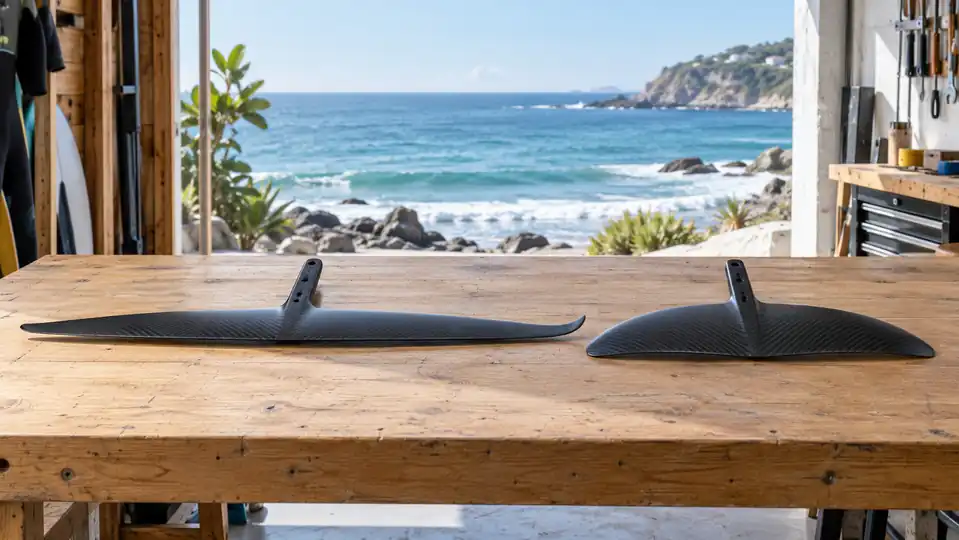
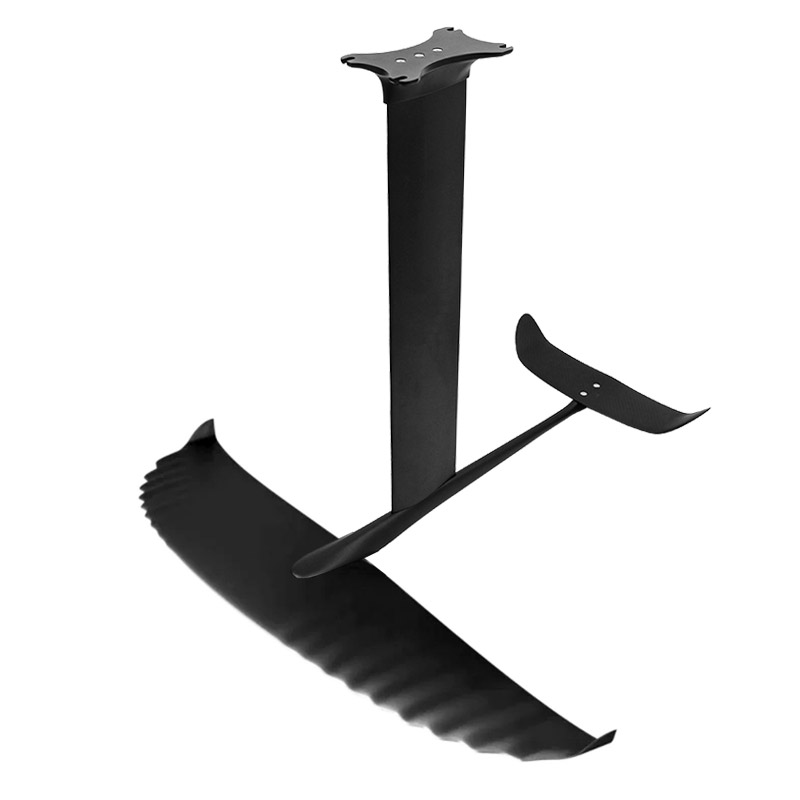
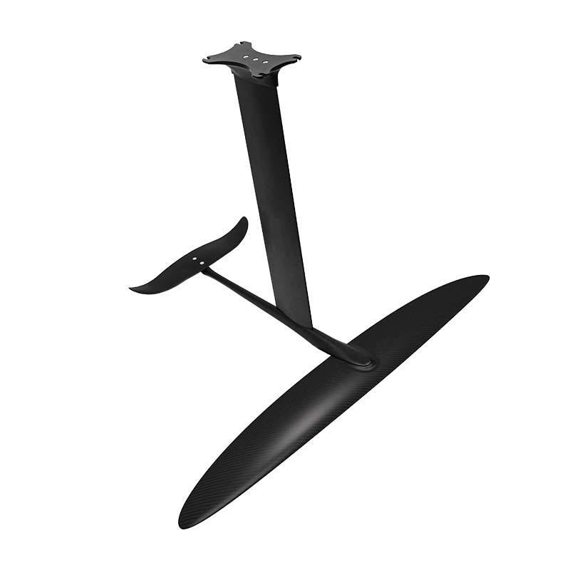
Confirm material form, minimum radius, ply segmentation, overlaps, debulking, cure route, trimming and inspection. Complex geometry may prevent a theoretically neat orientation from being placed repeatably. Unitysurf’s overview of composite hydrofoil manufacturing illustrates why design, tooling, layup, curing, machining and testing must be treated as one controlled process.
5. Validate the first article against agreed evidence
Dimensional inspection and surface appearance alone do not confirm the internal laminate. Depending on risk, evidence may include material certificates, frozen storage records, ply kits, traveler sign-offs, cure logs, witness panels, mass checks, ultrasonic or other NDT, cut sections, coupons, proof loading, fatigue testing or destructive qualification.
6. Lock changes after approval
Control material designation, supplier, areal weight, resin, ply orientation, sequence, splice rules, cure cycle, tooling and machining. A change that preserves the external shape can still change structural behavior.
What to include in a carbon-fiber RFQ
A useful RFQ lets a manufacturer distinguish a cosmetic component from a controlled structural laminate. Include:
- Part definition: 2D drawing, 3D model, revision and critical dimensions.
- 0° reference: datum, axis or edge that controls all ply angles.
- Use case: primary loads, secondary loads, supports, duty cycle and misuse cases to consider.
- Performance targets: stiffness/deflection, proof load, fatigue, mass and dimensional tolerances where applicable.
- Interfaces: holes, inserts, bonded areas, clamps, sealing faces and contact materials.
- Environment: temperature, water, salt, UV, chemicals and storage conditions.
- Material control: prescribed fiber/resin/prepreg or permission for a supplier proposal subject to approval.
- Laminate ownership: buyer-issued ply schedule or supplier-designed schedule with review gates.
- Appearance: weave direction, gloss, color, print, pinhole criteria and acceptable cosmetic variation.
- Verification: inspection method, sample size, coupons, proof tests, records and acceptance criteria.
- Commercial scope: prototype quantity, forecast, tooling ownership, packaging and change-notification rules.
If you are preparing a new composite program, Unitysurf’s custom carbon fiber manufacturing page explains available OEM/ODM development, molding, machining, finishing and project-review capabilities.
Questions buyers often ask
What is the best carbon fiber layup orientation?
There is no universal best orientation. The efficient laminate places fiber along the important load paths while providing adequate shear, transverse, local-interface and damage support. Geometry, environment, fatigue, manufacturing constraints and validation requirements decide the final schedule.
Is [0/45/−45/90]s always quasi-isotropic?
It is a common educational example of a balanced, symmetric orientation set that can provide quasi-isotropic in-plane extensional behavior when the plies have compatible properties and thickness. That label does not guarantee equal bending, impact, fatigue or through-thickness behavior, nor does it approve the sequence for a specific part.
Does a 3K twill surface mean the laminate is 0°/90°?
It describes the visible fabric tow size and weave, not the entire internal stacking schedule. The face ply can also be rotated relative to the part datum. Ask for the controlled ply definition or performance requirements.
Should 0° plies always be on the outside?
No. Outer plies have strong influence on bending stiffness, but surface damage, impact, machining, environmental protection, ply drops and other load directions also matter. Ply position should follow the complete design and validation case.
Can a supplier determine the layup from a CAD model?
A CAD model defines geometry, not loads, safety factors, fatigue, environment or acceptance evidence. A supplier can propose a laminate only after those inputs and design responsibility are agreed.
Build the specification before you build the mold
The central lesson is simple: carbon fiber does not provide generic strength. It provides directional reinforcement that must be placed, cured and verified around a known load path. Define the axis, loads, interfaces and evidence first; then review fiber form, angle percentages, stacking order and manufacturing controls as one system.
For an OEM feasibility review, send Unitysurf your drawing or 3D file, reference axis, load description, target quantity and validation needs through the project contact page. The first conversation should identify unknowns—not hide them behind a familiar-looking weave.
Editorial and technical note: This article summarizes established composite-laminate principles for sourcing and DFM conversations. Example stacks are explanatory only. Final design values and acceptance criteria must be based on the selected material system, manufacturing process, analysis and project-specific testing.