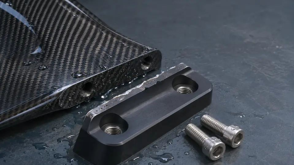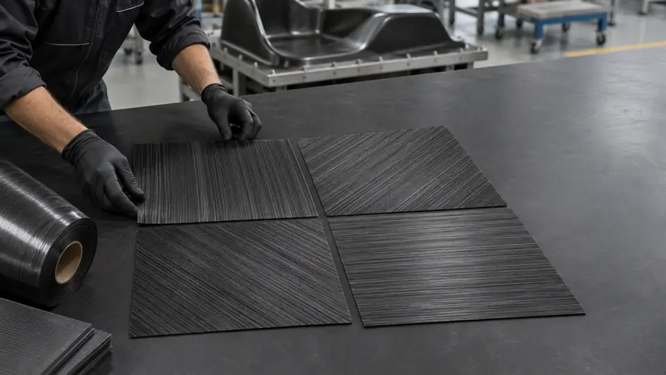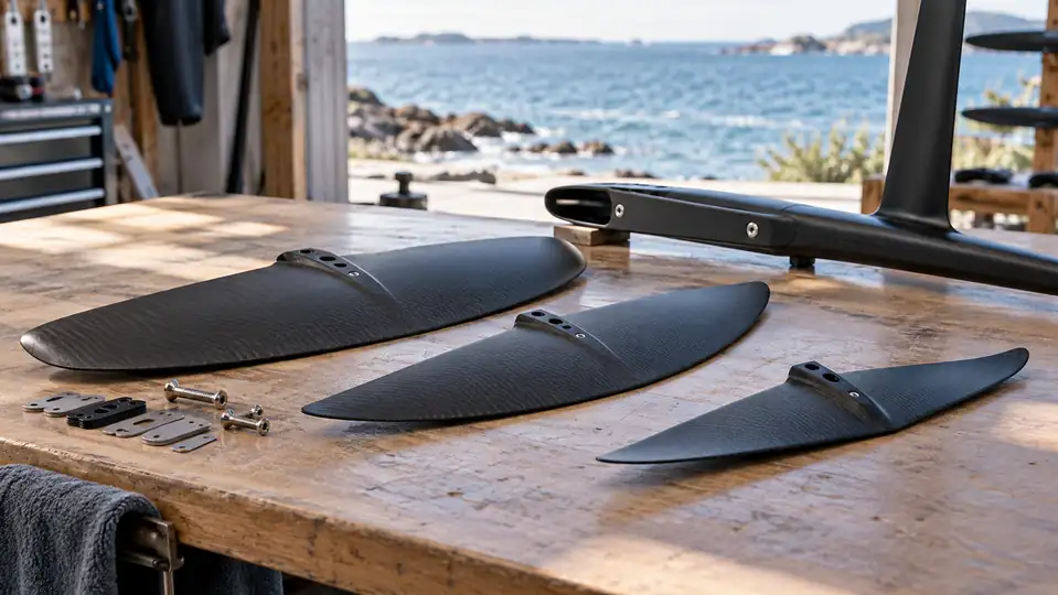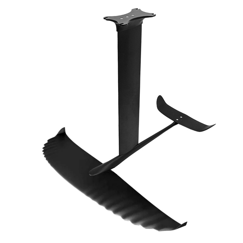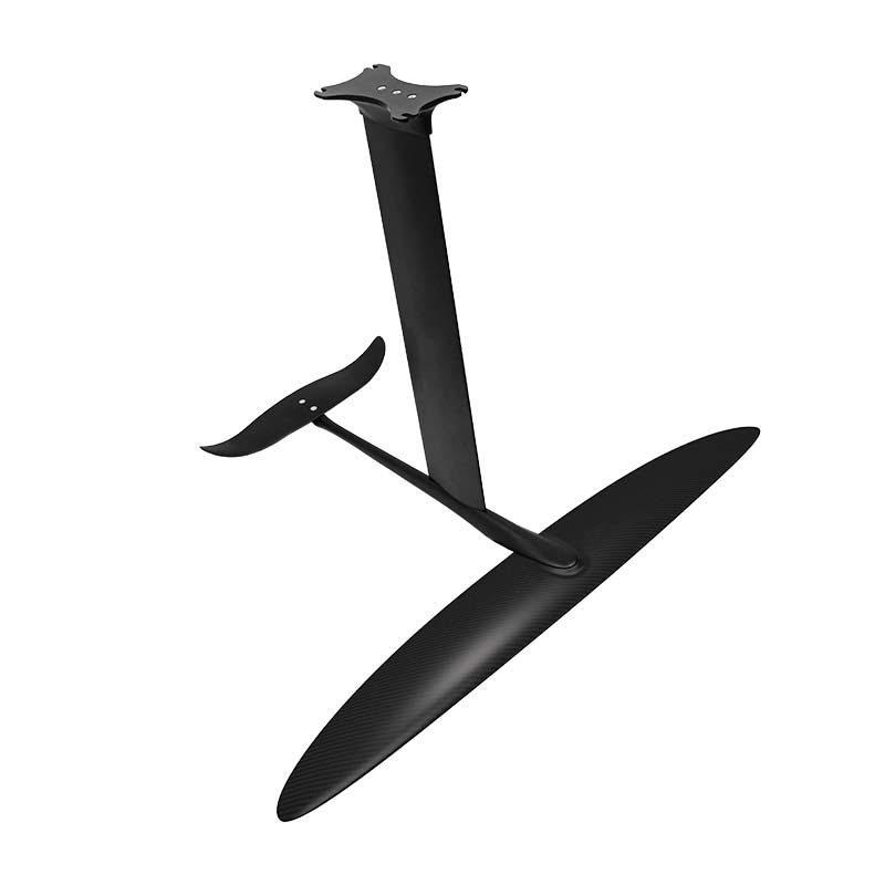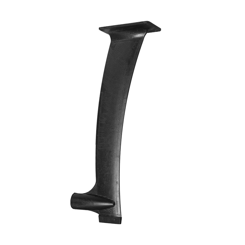
A hydrofoil mast profile is the complete cross-sectional shape of the mast—not just its maximum thickness. Chord length, thickness-to-chord ratio, leading-edge radius, maximum-thickness position, trailing-edge geometry, taper, laminate and internal structure all influence drag, bending, twist and control. That is why two masts labeled “14 mm” can feel noticeably different on the water.
The short answer
Do not select a mast from thickness alone. Compare the full section geometry, spanwise taper, bending and torsional test conditions, surface finish, connection stiffness and the wing/rider load the mast must carry. A thinner mast can reduce wetted frontal area, but it is not automatically faster, stiffer or more resistant to ventilation.
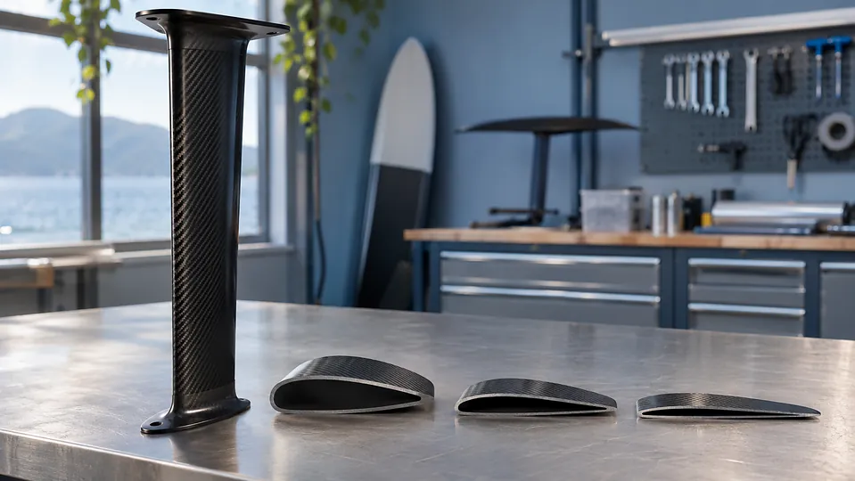
What Does a Hydrofoil Mast Profile Include?
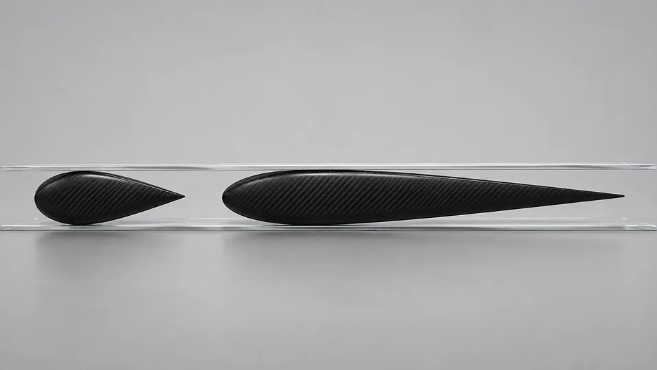
Viewed from above, a mast section resembles a symmetrical foil: a rounded leading edge meets the water first, the body reaches maximum thickness somewhere along its chord, and the surfaces converge toward the trailing edge. The dimensions are related, but each describes something different.
| Variable | What it measures | Why it matters |
|---|---|---|
| Chord | Leading edge to trailing edge | Affects wetted area, Reynolds number, internal structural depth and yaw response |
| Maximum thickness | Widest side-to-side dimension | Influences frontal area and the space available for skins, core and shear structure |
| Thickness-to-chord ratio | Maximum thickness divided by chord | Allows sections with different absolute sizes to be compared more meaningfully |
| Maximum-thickness position | Where the section is thickest along the chord | Changes pressure recovery and the volume distribution available to the structure |
| Leading-edge radius | Roundness of the nose | Influences sensitivity to yaw, surface damage and flow separation |
| Trailing-edge geometry | Thickness, angle and finish at the rear | Affects wake behavior, noise, durability and manufacturability |
| Spanwise taper | How chord or thickness changes from plate to fuselage | Lets designers place structure near high-load zones while reducing submerged area elsewhere |
One experimental study of a kitefoil/windfoil assembly used a symmetrical NACA 0009 mast section with a 112.5 mm mean chord and thickness equal to 9% of chord. Those values describe that research specimen; they are useful examples of the terminology, not a universal target for every riding discipline. See the dimensions and test scope in the Journal of Marine Science and Application study.
Why the Same Thickness Can Produce a Different Ride
Imagine two sections that are both 14 mm thick. If one has a 100 mm chord, its thickness ratio is 14%. If the other has a 125 mm chord, its ratio is 11.2%. The second section is proportionally slimmer, yet it also presents more chordwise surface to the water. Now move the thickest point aft, change the nose radius, sharpen the trailing edge or alter the taper: the flow and structural behavior change again.
This is why a catalog number cannot predict the whole ride. The F-ONE Carbon Mast 16 page, for example, discusses both a 16 mm profile and different fiber directions for bending and torsion. AXIS describes progressive thickness along some carbon masts. These are useful design disclosures, but specifications from different brands still need common test conditions before their performance percentages can be compared.
Absolute thickness and thickness ratio answer different questions
Absolute thickness helps describe frontal size and structural packaging. Thickness ratio describes the section’s proportions. Neither number identifies the leading-edge radius, pressure distribution, laminate stiffness or surface waviness. A fair comparison should record both dimensions and the chord location where they were measured.
The underwater section may not be uniform
A mast may be wider or thicker near the board connection, then taper toward the fuselage. That can place material where bending moment is highest while giving the lower immersed region a smaller section. Therefore, a single “maximum thickness” value may describe only one station. Ask for dimensions at several span positions.
How Profile Geometry Changes Drag and Glide
Profile drag is produced by pressure and skin friction as water moves around the mast. Reducing thickness can reduce frontal area, but total drag also depends on chord, wetted surface, speed, water condition, angle to the flow, surface finish and whether the boundary layer remains attached. “Thinner equals faster” is therefore a useful hypothesis, not a complete design rule.
A longer chord can provide more internal depth for a stiff structure and may make the section less sensitive in one operating range, but it also increases wetted area. A very short or sharp section may look fast in a dimension table yet become sensitive to yaw, damage or manufacturing tolerance. The best compromise changes with rider load, mast length, wing span and target speed.
Surface condition is part of the working profile
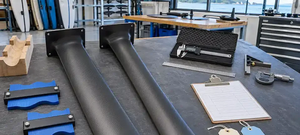
A perfectly modeled section does not remain perfect if the leading edge has chips, the laminate has print-through, the surface is wavy or a repair leaves a step. These deviations can alter local flow. Inspect both sides under low-angle light and use a contour template or scan when the program requires tighter repeatability. Do not aggressively sand a carbon mast to chase speed: sanding can change geometry, expose fibers and reduce protective coating.
Bending Stiffness and Torsional Stiffness Are Not the Same
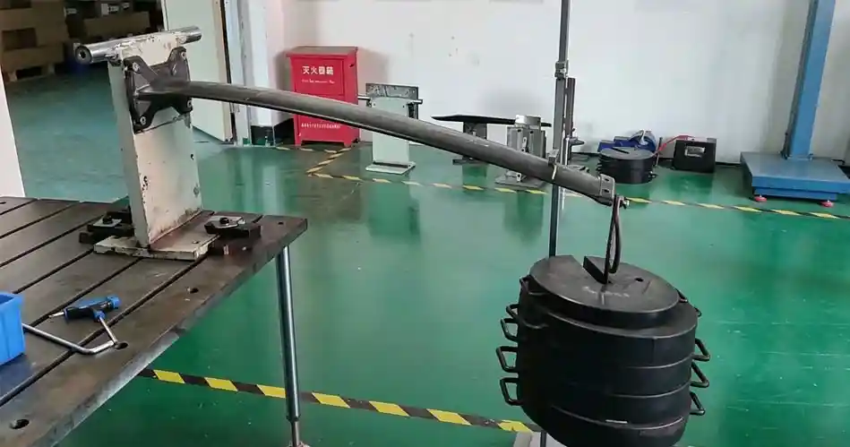
Bending is the mast deflecting sideways under load. Torsion is the mast twisting around its long axis. A mast can perform well in one direction and less well in the other. Riders may describe both as “soft,” but the on-water symptoms and design responses are different.
| Behavior | Possible rider observation | Variables to investigate |
|---|---|---|
| Excess bending deflection | Delayed response, load-dependent wandering or a less connected feel | Mast length, chord, laminate along the span, skin separation, rider and wing load |
| Excess torsional deflection | Yaw lag, vague roll-to-turn connection or unstable feedback under high side load | Closed-section geometry, ±45° reinforcement, internal shear structure and connections |
| Connection movement | A stiff mast still feels imprecise | Plate, fasteners, mast-to-fuselage interface, fit and local bearing stiffness |
Carbon grade alone cannot establish finished-mast stiffness. Geometry, fiber volume, laminate thickness, fiber orientation, core or shear web, cure quality and connection design all contribute. Our guide to carbon fiber layup orientation explains why 0° and off-axis fibers serve different load paths, while the existing high-modulus carbon mast guide focuses on material modulus and cost.
Does a Thin Hydrofoil Mast Profile Prevent Ventilation?
No single profile dimension guarantees that a mast will not ventilate. Ventilation involves atmospheric air reaching a low-pressure or separated-flow region along a surface-piercing component. Speed, yaw or angle of attack, waves, surface damage, contamination, junction geometry and the section itself can all influence the event.
A 2026 Journal of Fluid Mechanics experiment compared two simplified surface-piercing profiles and identified different nose, tail and base ventilation mechanisms across test conditions. The study supports an important caution: geometry and operating condition interact. It does not prove that one commercial water-sports mast will behave identically in waves, maneuvers or a different Reynolds-number range.
If a foil suddenly loses support or control, use the step-by-step checks in our hydrofoil ventilation guide. Do not diagnose the mast from thickness alone.
Choose Priorities by Discipline, Not by One “Best” Number
| Use case | Likely priorities | Questions to ask |
|---|---|---|
| High-speed racing | Low drag at target speed, controlled yaw, repeatable surface finish | At what speed and load was the profile evaluated? How are tolerances verified? |
| Large wings or heavier riders | Bending and torsional stiffness under higher moment | What deflection occurs at a stated load and lever arm? |
| Pump and downwind foiling | Efficient glide plus predictable energy transfer | How does the mast pair with the intended span and low-speed wing? |
| Surf and freestyle | Impact tolerance, responsive control, durable edges and connections | What are the inspection limits after impact and the repair policy? |
| Rental or school fleets | Durability, compatibility, easy inspection and controlled replacement cost | Which damage criteria remove the mast from service? |
The “fastest” standalone mast is not automatically the best system. A profile must work with the mast length, front-wing span, fuselage, connection standard, rider mass and operating envelope. Start with the system requirement, then choose geometry and laminate together.
How to Compare Two Hydrofoil Masts Fairly
- Match length and connection. A longer cantilever normally faces a different bending demand, and a flexible interface can dominate the result.
- Record chord and thickness at named stations. Measure near the plate, mid-span and near the fuselage rather than relying on one maximum value.
- Calculate thickness ratio. Divide thickness by chord at the same station and state the result as a percentage.
- Separate bending from torsion. Record fixture span, load position, applied load, direction and displacement or angle.
- Compare like-for-like surfaces. Note coating, damage, repairs and edge condition before any water test.
- Use the same board, foil and rider where practical. Change one variable at a time and record water state, speed range and maneuver.
- Describe uncertainty. A single rider impression is useful feedback, but it is not a universal performance measurement.

What an OEM Mast RFQ Should Specify
“Make a thin, stiff carbon mast” is not a complete engineering brief. A useful request for quotation connects the performance target to measurable geometry, loads and interfaces.
- Target disciplines, rider-mass range, wing span/area range and intended speed envelope
- Mast length, plate standard, fuselage interface and fastener requirements
- Chord, maximum thickness and thickness position at multiple span stations
- Leading-edge and trailing-edge requirements, including safe minimum edge geometry
- Allowed profile deviation, straightness, twist and surface-finish acceptance criteria
- Bending and torsional stiffness targets with fixture span, load, direction and measurement method
- Laminate material, orientation philosophy, internal core/shear structure and cure process to be agreed
- Environmental, fatigue, impact and salt-water exposure requirements appropriate to the product
- Sample quantity, inspection documents, test sequence and approval gates before production
Unitysurf’s hydrofoil mast manufacturing page shows the relevant product category, and the custom carbon fiber manufacturing page outlines broader OEM capability. A final design still requires program-specific drawings, loads, tolerances and validation criteria.
Do not accept an isolated stiffness percentage
“30% stiffer” is incomplete unless the baseline mast, length, fixture, load direction and calculation are defined. The same applies to drag-reduction claims: ask for the reference profile, speed or Reynolds-number range, yaw conditions, surface assumptions and whether the result came from simulation, a tow test or rider feedback.
A Practical Sample-Approval Workflow
- Freeze the drawing revision. Identify every sample and the geometry it represents.
- Inspect incoming dimensions. Record chord, thickness, taper, straightness, twist, interfaces and mass.
- Map the surface. Photograph edges and junctions under consistent light; document pores, waviness, chips or coating defects.
- Run structural checks. Use the agreed bending, torsion and proof-load methods without substituting an undefined shop test.
- Complete controlled water evaluation. Keep board, wing, fuselage, rider and conditions as consistent as practical.
- Inspect again. Check fastener torque, interfaces, coating and any new sound, movement or damage.
- Approve against criteria. Convert lessons into drawing tolerances and a repeatable production inspection plan.
Common Hydrofoil Mast Profile Questions
Is a 12 mm mast always faster than a 16 mm mast?
No. Thickness affects frontal size, but chord, section shape, wetted area, surface condition, yaw and operating speed also affect drag. The thinner option may also require different materials or internal structure to meet the same stiffness target.
Can carbon grade compensate for a poor profile?
Higher-modulus fiber can support a stiffness target, but it does not correct an unsuitable pressure distribution, rough surface, inaccurate geometry or flexible connection. Material, shape and manufacturing quality must be designed as one system.
Should the trailing edge be razor sharp?
A thin, accurate trailing edge may reduce wake disturbance, but an impractically sharp edge can be fragile or unsafe. The specification should balance hydrodynamics, structural durability, manufacturing repeatability and handling safety.
What is the most useful first comparison metric?
Start with a geometry table at common span stations, then compare bending and torsional deflection under identical fixtures and loads. That creates a stronger baseline than a single maximum-thickness number.
The Better Question Is Not “How Thin?”
The better question is: which hydrofoil mast profile delivers the required drag, bending stiffness, torsional control, durability and manufacturability for this complete foil system? Thickness is part of that answer, but chord, thickness ratio, edge geometry, taper, laminate, internal structure, surface accuracy and connections determine whether the design works as intended.
For an OEM discussion, bring the intended discipline, rider and wing load range, connection drawings, target dimensions and test criteria. Review the complete hydrofoil product range, or contact Unitysurf with a drawing and sample-validation plan.
Technical scope: This guide explains design variables and comparison methods. It does not publish a universal section, stiffness target or safe load for every mast. Final geometry, laminate, proof loads and inspection limits should be validated for the intended foil system and use case.